Please take proper safety precautions when dealing with electronics and soldering. Have proper ventilation and a clean work area. Research basic soldering technique if in doubt. I cannot be held responsible for any damages that could occur to you or your equipment while following the procedures present on this Website.
Why Upgrade?
The N64 did not output RGB when released. Once upgraded the N64 puts out the best analog video signal possible.
Special Note: Some of the images in this guide show older kits. The install method is the same.
This RGB amp only works for the early N64 consoles. Look for serial numbers starting with NS1. These early model contain compatible mothers boards marked NUS-01, NUS-02, NUS-03 & NUS-04
Kit & Tools can be purchased here
Supplies Needed:
- Small piece of electrical tape.
- Soldering skills!
- The 4.5mm bit that opens the console
- Philips head screwdriver
- Soldering iron & solder
Read this Awesome "Soldering is Easy – Comic" for Basic 101s of soldering click here.
Installation:
Start by removing all 4.5 bit screws from the bottom side of console. There are six total. Also remove the jumper pack before separated console shell.
Next, Remove all screws around the motherboard as shown in photo (red dots only). Make note of different screws sizes and keep them organized. View my photo for reference.
Now it is time to prep the RGB amp. The back side of the board has no exposed conductive metal. Though to insure reliability I prefer adding a piece of electrical tape to the section shown in the photo.
Next, Place the RGB Amp over the multi-out pins. Make sure it slides over all the pins.
Add Solder to all 12 pins.
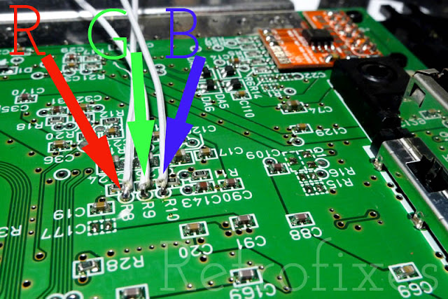
Next, locate this spot on the motherboard:
This location is very important, study it closely before soldering. Each hole is labeled on the motherboard. R8=Red output , R9=Green output, R10=Blue output. If this location is not on your motherboard you do not have an early NS1 N64.
Soldering hookup wire: Measure and cut the wires to proper length and solder them to the corresponding pads on the Amp. Most prefer to strip the wire and slightly twist the strands. Next add a small amount of solder to wire tip. Trim wire tips to very small 2-3mm in bare length. Using long wires in the R8/R9/R10 vias will cause malfunction and touch another IC chip.
Do this to every wire before soldering to it's location. This is called "tinning" your wire. Very important step and makes you installation cleaner and more reliable.
Solder each wire to the locations shown. Beware of large blobs of solder, work patiently.
Avoid long leads and do not allow uninsulated wire to touch surrounding parts on the motherboard.
Next add a small amount of solder to each RGB pad on the pcb amp.
Next, solder each R/G/B wire to the corresponding amp pad. Keep the wire tips short to avoid hitting the metal RF shield when replaced.
N64RGB Pads Explained
R=Red Input
G=Green Input
B=Blue
Csync
Note: N64 motherboard revisions NUS-CPU-01, NUS-CPU-02 and most NUS-CPU-03s usually have csync routed to the multiout. No extra wires required.
Csync on NUS-CPU-04 motherboards usually require a 4th wire.
How to confirm:
View R16 on the motherboard. If the surrounding pads are populated it has snyc. If the pads are unpopulated you will need a jumper wire. View photos below
 |
| 4th wire needed. Example of unpopulated components at r16. |
 |
| Populated components surrounding R16. NO jumper wire needed. |
Now it is time to replace the bottom metal shielding. The Amp is very slim and designed to rest beneath the edge of the shielding as seen in the photo. Make sure your wires are not touching the underside of metal shielding. If the shielding is hitting the amp or wire you can gently bend the shielding tab out of the way.
 |
| Make sure the wire is not pinched by the metal RF shield! |
Remember, the memory module has to be plugged in, or the N64 will not boot.
Done! Reassemble your console and start testing some games!
Your RGB N64 is now compatible with any scart csync cable configured for TTL. (the most common cable design)


