Why Upgrade?
The original system system had poor RF video quality. Many new HDTVs will not recognize vintage RF video signals. With this upgrade your sound and video will be much more crisp and clear.
Purchase the Kit Here.
Disclaimer:
Though this job is a pretty easy task, it requires that you do some soldering of some wires and connections. If you are not skilled with a soldering iron, please send your console here for a full upgrade service! I cannot be held responsible for any harm you do to yourself or to your game console. Please contact us for installation services if in doubt.
Before Starting.
Please leave your console system at the ON position for at least 30 minutes with the power cord unplugged.. Please do not skip this stage! These consoles have large capacitors inside and they need to be discharged before doing any repairs/upgrades. Otherwise, you may get shocked by accidentally or unintentionally touching them
Read this Awesome "Soldering is Easy – Comic" for Basic 101s of soldering click here.
Tools:
• Drill with 1/4” & 3mm drill bit
• Ruler
• Marker
• Soldering iron, solder, and solder braid
• X-Acto knife (optional)
• Needle-nose pliers
• Flat head screw driver (Adjustable wrench needed on some models)
Installation:
First,
Turn the console over and remove the 3 screws (or bolts). I have seen several different variations with the console. Separate the halves gently and carefully.
Most models will have the metal RF shielding as shown below (if not lucky you). De-soldering and removing this shield can be challenging
Before we can remove the RF shielding make sure to unplug all the input controllers, power cable and rf box. The old cables can be fragile, do not force anything. Note: The large RF box as shown in lower left corner can be removed and discarded. If you leave it in-place do not plug it in after upgrade.
Also be careful with the old vintage ribbon as shown below. On most models it is easy to unplug. If you decide to leave it plugged be very careful while desoldering the RF shielding.
Desoldering Tip:
The RF shielding is held by several surrounding solder points.
I find it much easier to heat the old solder while simultaneously lifting the shielding as shown below. Do this for each tab surrounding the motherboard
Step 5:
Once the shielding is removed we can solder in the kit. The soldering area is highlighted by the pink outline.
Next solder the included wire to the amp kit. The ribbon wire can be easily separated if snipped between each wire. Insert the wire into the top of the kit and solder from the bottom. Your results should look like the photo below.

Next solder the inputs "IN" wires from the kit to the locations shown below.
KIT ID PINOUT:
5V = 5V POWER
VI = VIDEO IN
AI = AUDIO IN
G = GROUND / GRD

The completed soldering should look like the photo below. Final install location of the kit is optional. I prefer using the foam tape and adhering it to the location shown. Make sure the surface is clean before sticking into place. Make sure the metal contacts on the amp kit are not touching the motherboard.
If you decided to reinstall the bulky RF shielding (optional) be mindful of the location of kit and wires. A small slot or hole for wires might need to be added to the RF shielding. Personally I decided not to reinstall the RF shielding on my model.
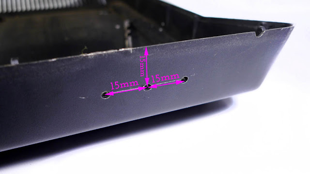
Next we need to drill some hole for RCA jacks. Jack locations is best at the left hand side of the bottom shell. Follow the photo below for reference.
I find 15mm from the top lip is perfect RCA placement
Also 15mm spacing from each jack. You can make small marks with a sharpie marker. Drill small 3mm holes first. Then drill the final 1/4" holes.
Example of Gold jacks installed.
Next we need to solder the "OUT" side of the kit to the RCA jacks.
G = Ground connection for each ground tab on RCA jacks. (tear drop shaped metal pieces)
VO = Video Composite out, solders to yellow RCA jack.
AO = Audio Out, solders to both the Red and White RCA jack.

After the RCA jacks are solders we are almost done :)
Now we can plug in all the controller ports, ribbons and power switch. Note: If you decided to keep the RF box inside the console, do not plug it back into the motherboard.
Color / Brightness Adjustments:
If you do not like the final video output you can make adjustments via the dial shown below. I would suggest making these adjustments before assembling the device. Though be very careful while powering on and operating a open console!
If your mod doesn’t work, go back and double-check your wiring.
Also make sure your games and cartridge port is clean.


This comment has been removed by the author.
ReplyDeletehas anyone ever thought about doing mod chips on the first gen systems?
ReplyDelete